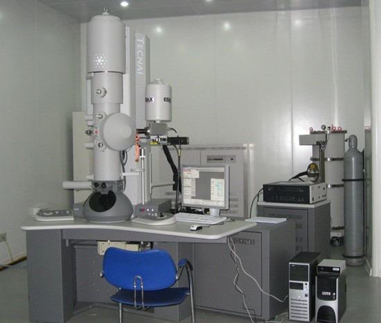
Name: Tecnai G2 F20 field emission transmission electron microscope
Manufacturer:FEI Company
Purchasing date: June, 2, 2008
Main Specifications:
1. point resolution: 0.24nm; line resolution: 0.14nm
2. The objective lens spherical aberration coefficient: 1.2mm;
3. The objective lens chromatic aberration coefficient: 1.2mm;
4. Amplification factor: 0.25 million to one million times;
5. Maximum inclination angle: ± 40 °.
Common accessories: EDS, HAADF probe, CCD camera
Main application area: microstructure tests on magnetic samples of steel and iron materials
Main usage: Tecnai G2 F20 S-TWIN, developed by FEI Company, is a new field emission transmission electron microscope with real multi-functions and multi-user environments. It flexibly integrates various transmission electron microscopy techniques (including TEM, SAD, STEM, EDX spectral imaging, etc.) to obtain stronger analysis functions. Adopting Schotty field emission electron gun which has high emission current, the machine can capture images with high brightness and good stability. It can be applied in the observation and analysis of material microstructure, morphology image analysis, electron diffraction image analysis, HRTEM high resolution image analysis, STEM analysis and EDX spectrum analysis.
Person in charge of the equipment: Zhang Weina
Ways of contact:
Tel: 13604028597 / 024-83686411
E-mail:
Location: 101, RAL
Brief Operation Rules
I. Starting up
1. Check and make sure the room temperature is within the range of 16 ~ 22 ℃, cooling water temperature is lower than 21 ℃, humidity is within the range of 30 ~ 50%, buoy of CCD pressure is normal, and EDX liquid nitrogen tank indicator is green.
2. Check the host power, vacuum and high pressure buttons. Normal states are as follows: ‘On’--green light dark; ‘Off’-- red light on; Vac. -- white light on; HT -- white light on.
3. Check two switches: CCD camera power supply, and CCD coding power
4. Login user, and open the following software successively:
a Tecnai user interface
b Digital Micorgraph
c Tecnai IA
d EDX
Ⅱ Insert and pull out the sample holder
- Set the objective lens diaphragm and diffraction lens diaphragm on neutral gear and set the value of sample holder coordinates x, y, z, and α and β angles to be zero.
- Double-tilting sample rod installation:
First, manually connect cable, and the type of sample holder would be selected by program. Check the cable connection, and wait for the red light on the sample holder shelf going off. Then, when the sample rod comes to five o’clock position, insert the lens tube into the lens barrel without turning. The red light is on, and Turbo starts automatically (orange). Three minutes later, Turbo starts to work (light yellow). After the red light is off, turn the sample rod counterclockwise to still,and then send the rod slowly into the lens column with the suction.
Take down the sample rod: first, set the value of sample holder position x, y, z, and α and β angles to be zero and directly pull out the sample rod out till it can no longer be pulled; Then turn clockwise till it cannot be turned any more, pull out the sample rod and take down the cable. Select the state of ‘no sample rod’.
- While using the single tilt holder, the alternative option of the sample sod in software is in default state. No need to connect the cable. (Note: Never use a single-tilting sample holder to observe magnetic samples!)
- When the column vacuum value is steadily lower than 20 (when it is totally stabilized, the value is 6), start the experiment.
Press “Col. Valves Closed” button in “Vacuum (User)”
- Turn on V7 Valve, namely, click “Set up”.
III. Basic sympodium
- Place the sample at the optimum height—“Eucentric Height”, and find the right position of the sample, and move the sample to the small circle labeled near the center of the screen. The amplification factor is 50 thousand to 100 thousand times.
Method 1: press "Eucentric Focus" and adjust Z ± axis on the right operator panel to make the sample close to focus position.
Method 2: Use α-Wobbler and adjust Z ± axis on the right panel to keep the sample from swaying with the sample stage.
- Mechanically adjust light spot to concentric convergence, and then adjust C2 X-, Y-axis of C2 diaphragm. This time, the magnification is about 40k times.
- If the beam spot is not round, adjust Condenser Astigmatism till it is round.
- Adjust Direct Alignment.
(a) Adjust Gun Tilt exposure time (S) to the minimum by multifunction key-Multi XY.
(b) Adjust Gun Shift 2-6 sympodium and Spot Size 2 (beam spot bright) with Multi XY; adjust Spot Size 6 ( beam spot dark) with Beam Shift.
(c) Adjust Beam Tilt PPX and Beam Tilt PPY in two directions. Control key: Mx.y.
(d) Adjust Rotation Center (which has great influence on resolution) to be above 20 times to vibrate concentrically, with the key Mx.y
IV. CCD image observation and acquisition (TEM bright-field and high-resolution TEM image)
- First, put the sample at the optimum height, press "Eucentric Focus".
- Find the required sample and choose an appropriate magnification to make the sample locate near the small circle marked in the center of electron microscopy host screen.
- Spread beam spot to full screen, and then lift the screen.
Press ‘Preview’ button in ‘CCD/TV Camera’ window, wait CCD to collect sample images and show the data in DM window. ® CCD® Click Workset in Microscope Control Software
- Turn “Intensity” on the left control panel, and adjust CCD image to proper brightness. Carefully adjust “Focus” on the right control panel to obtain the best focal length.
- Click “Acquire” button in CCD/TV CAMERA to capture TEM bright field image.
- Collect high-resolution TEM image
- Adjust astigmatism in 0.3 million to 0.4 million (35k ×) times and collect image by CCD. Adjust Mx.y with the combination of "Live -- FFT" to make amorphous ring round in amorphous areas.
- Adjust Coma Free in 0.3 million to 0.4 million (35k ×) times and collect image by CCD. Adjust Mx.y with the combination of "Live -- FFT" to make the two amorphous rings in amorphous area be the same.
- Click “Acquire” in CCD/TV Camera to acquire high-resolution image.
V. Completion of experiment
- Magnification: Back to SA mode, zoom 38000 ×, light spot spreading
- Close V7 (Click “Col. Valves Closed” in “Set up Vacuum(User)”) and cover the observation window.
- Exit lens aperture and area-selected aperture.
- Sample stage return to zero: click “arrow” on the top right on the “Search” window, and then click “Holder” to check x, y, z values on the bottom right corner of the screen and α and β angle to be back to zero.
- Unplug the sample stage: unplug it and clockwise turn it to unmoving respectively. Then pull it out in the vertical direction.
- Bake nitrogen: 1) Remove the liquid nitrogen tank;
2) Click on the arrow on the top right corner of ‘Set up Vacuum (User)’ window; click the button Cryo Cycle and wait for the turbo molecular pump start (the button “Turbo on” turns from gray to yellow).
7. Close the LCD monitor
Instructions: the operating software of this machine is Microscope Control. If the software interface button is yellow, it indicates the function controlled by this button is in operation. If the button is grayed out and the word is black, it indicates that the function represented by the button is on standby state; If the button is grayed out and the word is in light color, it indicates that the function is not yet available.
Precautions:
- Special attention should be paid to the Beam intensity while using CCD to capture the electron diffraction.
- Please refer to other documents about dark field, EDX, STEM, EELS, etc.